The underlying technology that drives CORE (including COREsim) includes:
CORE’s integrated system design repository supports the many individuals who are adding, deleting, changing, and reviewing design information that results in the specification of a system. This centralization allows all team members to work from a common, controllable baseline. Additionally, this approach is key to providing consistency of the elements in the system design and assures that all design views (graphic and otherwise) are always synchronized and consistent.
Our approach to attaining an explicit system specification is grounded in the use of the System Definition Language (SDL) provided with CORE. SDL is a formal, structured language which avoids the ambiguity inherent in using common English to define or specify a system. The precise meaning of each language concept is fixed and documented to enhance team communication and assure unambiguous interpretation of specifications using this language. The repository is structured by the SDL which is user extensible, if needed. SDL is an Element-Relationship-Attribute (ERA) language augmented by graphical structures with semantic meaning. SDL is based on the following primitive language concepts:
The repository consists of elements that are modified by attributes and related to other elements. This structure corresponds to the object-oriented approach. Elements are represented as objects with the attributes stored as data within the objects. The relationships then define the interaction between objects.
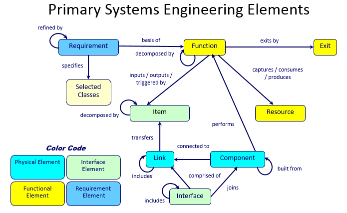
In CORE, the SDL is referred to as a schema (or the project metadata). The diagram below illustrates a subset of the basic schema, showing some of the primary systems engineering classes and relationships between them.
CORE dynamically generates diagrams directly from the system design repository ensuring that they are consistent with current design details. A change made in any view changes the design information in the repository and, conversely, a change made to the database is automatically reflected in the views.
CORE delivers a mixture of SysML and traditional representations enabling you to satisfy the specific needs of your project. CORE provides the following diagrams of interest to engineering and management personnel permitting system models to be viewed in as many layers of abstraction as necessary to understand the model:
Element Relationship (ER) Diagrams: display the element and its relationships to other elements
Hierarchy and Spider Diagrams: graphically display several layers of relationships between elements on a single diagram such as functional, physical, and traceability hierarchy views.
Package Diagrams: display arbitrary clustering of model elements to communicate groupings and interrelationships of interest
Requirements Diagrams: show system requirements and their relationships to logical and physical components of the solution
Use Case Diagrams: describe the functionality of a system in terms of how its users interact with the system to achieve their goals
State Transition Diagrams: reflect system states, the transitions that connect them, and the events that trigger transitions
Function Flow Block Diagrams (FFBDs): show functional flow including control logic
Activity Diagrams and Enhanced Function Flow Block Diagrams (EFFBDs): portray behavioral flow, control logic, and inputs/outputs/triggers
Sequence Diagrams: represent the interactions between functions and their corresponding components
Integration Definition for Function Modeling (IDEF0) Diagrams: show functions, inputs, outputs, controls, and mechanisms
N2 (N-squared) Diagrams: display functions/components and their internal and external interactions in a matrix format
Block Definition Diagrams: show composition and classification of the physical architecture
Physical Block Diagrams, Interface Block Diagrams, and Internal Block Diagrams: show composition and connectivity (both physical and logical) of the physical architecture
The CORE report generator enables you to extract information from the CORE system design repository and present it in virtually any desired format. Reports allow you to view the system design information in different ways. Reports in CORE can range from a simple query (e.g., a list of all open concerns) to complex, formal documents (e.g., a System/Segment Specification). Reports and analyses for engineering or management support are generated through the use of more than fifty standard utilities, queries, and report templates provided with CORE. Reports in CORE can be generated in any ASCII-based text file format. Most reports are generated using Rich Text Format (RTF) (a standard publication file format) that can be imported into word processors such as Microsoft Word® for previewing, editing, and printing.
The structure of a report is controlled by a report script that instructs the report generator how to query the system design repository to gather data and how to format the information for each portion of the report. Users can develop custom reports, queries, and interfaces to other tools as well as customize the standard scripts provided with CORE. Scripts are written using the COREscript language. Full documentation of COREscript can be accessed via the CORE Help menu. Also, Vitech offers a 2-day class that focuses on exploiting the power of the COREscript language.