
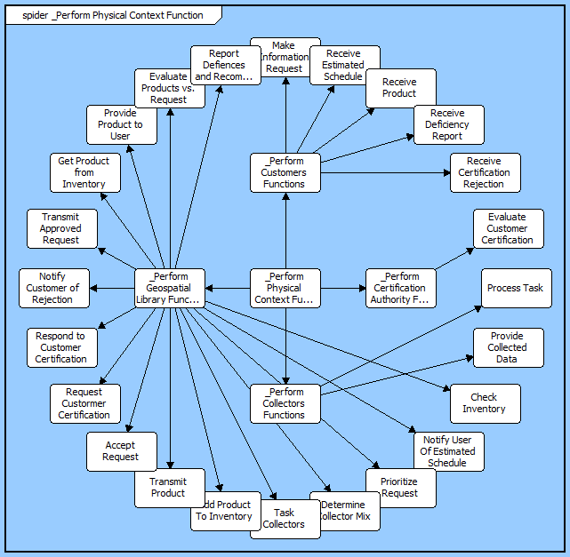
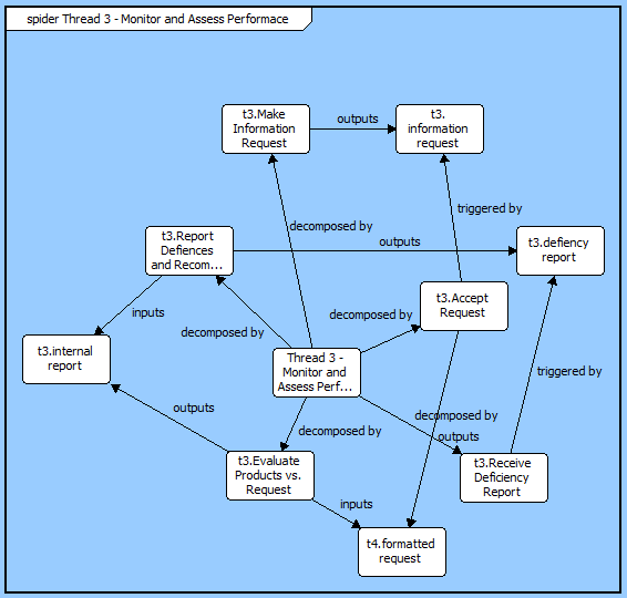
The spider diagram provides a complete contextual view of a set of elements and their interrelationships. Part of the general representation set, this diagram blends concepts present in an ER diagram (displaying relationships relative to an entity of interest) with concepts of a hierarchy diagram (showing multiple levels of relationships). Unlike a hierarchy diagram, each entity is represented once and only once. In addition, the freeform presentation does not artificially imply a hierarchical relationship that may not exist. The result is an extremely powerful representation – neither traditional nor SysML – for analysis and communication.
A spider diagram is opened on the combination of an element and a hierarchy definition. The element defines the starting point for the diagram. The hierarchy definition specifies the relations (and optionally target classes) to traverse when building the spider diagram. The diagram will open to number of levels specified with each element encountered displayed on the diagram once and only once. The relationships between the elements are then shown as connecting lines.
 |
Elements are drawn only once on the diagram, potentially representing multiple relationships. If you select a node on a spider diagram and ask to remove it, you will remove all relationships which connect it to elements on the diagram. If you wish to remove just a single relationship, select the associated label and use the Remove Target command. |
The spider diagram is a free-form diagram. The diagram supports many different vertical and horizontal layouts selectable from the diagram options or the layout command. Switch between layouts to select your preferred starting point and then customize node positions as desired. Individual nodes can be moved anywhere on the diagram. In addition, individual relation line labels can be moved. When the label separates too far from the relation line, a "lightning bolt" will draw to automatically connect the label its corresponding line.
In addition to the classic diagram options, the spider diagram settings include:
Show Relationship Names - controls whether relationship names (aliases, if defined) are displayed on the relationship lines indicating the relationship between the connected nodes. When the objective is simply to understand the connectivity of elements (but not the specific nature of the interrelationships), toggling off the display of relationship names will minimize clutter on the diagram and increase readability. Note that the initial value for this setting is drawn from the specified hierarchy definition and is then controlled by the diagram option.
Layout - controls the default diagram layout to use with the diagram. Available diagram layouts options include vertical trees, horizontal trees, circular, radial, and more.
Levels - controls the initial number of levels to show on the diagram. Individual nodes can then be expanded or collapsed, as desired.
The constructs tab allows you to quickly decorate your spider diagram, while the all entities tab enables you to relate your diagram elements to the remainder of your system definition.
Constructs
New Information Block - drop onto the diagram to insert an information block (a mini property sheet)
New Note - drop onto the diagram to insert a new note (descriptive text in a note icon)
New Shape - drop onto the diagram to insert a new shape (a rectangle, rounded rectangle, circle, or ellipse with text, if desired)
New Graphic - drop onto the diagram to insert a new picture
All Entities - all classes and elements in the system model, allowing you to drag any element on top of a diagram node to establish relationships with the balance of your system model
Insert
Open Element view submenu