
The hierarchy diagram represents the relationships between several layers of elements. There is no pre-defined semantic for a hierarchy, allowing the user to define the specific set of relationships to deliver the desired representation and insight in a traditional representation. Sample uses include functional, physical, and traceability hierarchy views. Part of the general representation set, hierarchy diagrams are available for all elements.
A hierarchy diagram is opened on the combination of an element and a hierarchy definition. The element defines the starting point for the diagram. The hierarchy definition specifies the relations (and optionally target classes) to traverse when building the hierarchy diagram. In building the diagram, CORE starts with the top-level element and checks to see if any of the specified relationships have targets of the specified target classes. If so, these targets become children of the top-level element and are displayed on the second level of the diagram. The children of the elements on the second level are then determined. This process continues until the lowest level elements have no targets in the specified set of relations. Individual elements are shown as nodes with the relationships between the elements shown as connecting lines.
The hierarchy diagram uses a structured layout with specific movement rules for each node. However, multiple vertical and horizontal layouts are available, so select the one that best fits your specific style and the specific data set.
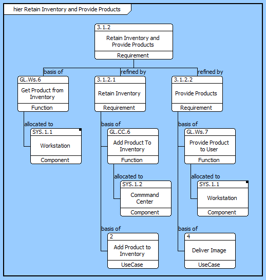
In a hierarchical format, if the same element is encountered multiple times when traversing the database, it is shown on the diagram multiple times. This presents a clean representation and avoids "string art" of crossing lines. When an element appears in multiple places on the diagram, a small black square appears in the upper-right corner of the icon. In this event, CORE proceeds to expand the first occurrence of the element.
A node with a black square in the upper-left indicates that there is more information to display. This can occur if there are more relationships to traverse than the number of levels specified for the diagram. This can also occur if you collapse an existing node to hide the nodes beneath it. Individual nodes can be expanded or collapsed as desired to tailor the representation.
In addition to the classic diagram options, the hierarchy diagram settings include:
Use Compact Placement - controls whether a compact placement algorithm is used when laying out the diagram.
Use Orthogonal Lines - controls whether orthogonal lines or direct lines are used to connect nodes on the diagram.
Layout - controls the default diagram layout to use with the diagram. Available diagram layouts options include vertical trees, horizontal trees, and more.
Levels - controls the initial number of levels to show on the diagram. Individual nodes can then be expanded or collapsed, as desired.
The constructs tab allows you to quickly decorate your hierarchy diagram, while the all entities tab enables you to relate your diagram elements to the remainder of your system definition.
Constructs
New Information Block - drop onto the diagram to insert an information block (a mini property sheet)
New Note - drop onto the diagram to insert a new note (descriptive text in a note icon)
New Shape - drop onto the diagram to insert a new shape (a rectangle, rounded rectangle, circle, or ellipse with text, if desired)
New Graphic - drop onto the diagram to insert a new picture
All Entities - all classes and elements in the system model, allowing you to drag any element on top of a diagram node to establish relationships with the balance of your system model
Insert
Open Element view submenu