
The IDEF0 diagram presents an integrated picture of the inputs, control, outputs, and mechanisms (ICOM) for a function's decomposition. Part of the behavioral (logical architecture) representation set, the IDEF0 diagram displays a great deal of context information on the interrelationships of the decomposition without displaying the actual control logic / structure of the decomposition. Originally specified by National Institute of Standards and Technology (NIST) Standard FIPS-183, the IDEF0 diagram is used less frequently than other behavioral representations but is still a valuable part of an integrated representation set.
The IDEF0 diagram is available for elements in the Function class (as well as any other subclasses of ProcessingUnit).
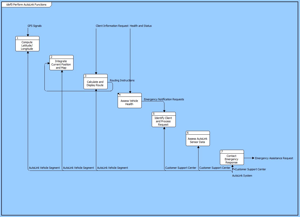
On an IDEF0 diagram, the subfunctions are shown on the main diagonal. The order of functions is automatically determined by CORE which traverses the underlying structure of the parent function (as shown graphically in an activity diagram or EFFBD). The structure is traversed left to right with parallel and select constructs traversed one branch at a time.
For each functional node:
 |
The IDEF0 A-0 variant (pronounced "A minus zero") provides a contextual ICOM view of a function at any level in your behavioral hierarchy. Though related in concept, the representation differs from the primary IDEF0 and is implemented as a separate diagram in CORE. |
The ICOM representation on an IDEF0 diagram has two special aspects:
Branching - Individual ICOM arrows fork and join on the diagram. Where an arrow forks, that represents the relationship between a parent element and a child element. Where two arrows join, that represents the relationship between a child element and a parent element. In this way, the IDEF0 diagram elegantly represents multiple levels of hierarchy in items and components, bringing additional clarity to the model.
Tunneling - Tunneling is a technique within IDEF0 to hide an ICOM in part of the model. The use of parentheses around either the head or tail of an arrow depicts a tunnel in IDEF0. A parenthesis around the head of an arrow that is entering a function box indicates that the ICOM associated with that arrow will not be seen on the decomposition of that function. If the ICOM does reappear, it will have parentheses around its tail. CORE handles this issue automatically. To insert a tunnel, just remove the item on the child page, and then CORE automatically inserts a tunnel on the head of the arrow on the parent page.
An IDEF0 model should have a purpose and viewpoint. These are usually placed on the context page. In CORE these can be inserted by using the Insert Note command.
| |
A good reference for further information on the IDEF0 diagram is National Institute of Standards and Technology (NIST), Federal Information Processing Standards Publication 183 (FIPS PUB 183), Specification for Integration Definition for Function Modeling (IDEF0). |
In addition to the classic diagram options, the IDEF0 diagram settings include:
Show Box Numbers - controls whether or not to display IDEF0 box numbers in the lower-right corner of every icon.
Use DRE - controls whether a Detail Reference Expression (DRE) instead of a decomposition box in the upper right corner to represent that an additional layer of detail exists. If the DRE is used, the element number is displayed below the lower-right corner of the icon to indicate the number of the decomposition diagram for the element.
The constructs and key entities tabs allow you to quickly develop your IDEF0 diagram, while the all entities tab enables you to relate your functions, items, and components to the remainder of your system definition.
Constructs
New Node - drop onto the diagram background to create a new function as part of the diagram decomposition (decomposed by)
Nodes - drop onto the diagram background to add an existing function as part of the diagram decomposition (decomposed by)
New Input - drop onto any function node to create a new item as an input (inputs)
Inputs - drop onto any function node to add an existing item as an input (inputs)
New Control - drop onto any function node to create a new item as a control (triggers)
Controls - drop onto any function node to add an existing item as a control (triggers)
New Output - drop onto any function node to create a new item as an output (output from)
Outputs - drop onto any function node to add an existing item as an output (output from)
New Mechanism - drop onto any function node to create a new component as a mechanism (performs)
Mechanisms - drop onto any function node to assign an existing component as a mechanism (performs)
New Information Block - drop onto the diagram to insert an information block (a mini property sheet)
New Note - drop onto the diagram to insert a new note (descriptive text in a note icon)
New Shape - drop onto the diagram to insert a new shape (a rectangle, rounded rectangle, circle, or ellipse with text, if desired)
New Graphic - drop onto the diagram to insert a new picture
Key Entities
Component - drop an existing component onto a function node to assign the component as the mechanism (performs)
Function - drop an existing function onto the diagram background to it as part of the diagram decomposition (decomposed by)
Item - drop an existing item onto a function node to relate it to the node using the input to, triggers, or output from relation
All Entities - all classes and elements in the system model, allowing you to drag any element on top of a diagram node to establish relationships with the balance of your system model
Insert
Edit ICOM
Open Element view submenu