
The IDEF0 A-0 (pronounced "A minus zero") diagram presents a context-level view of the inputs, control, outputs, and mechanisms (ICOM) for a specific function in your logical model. Part of the behavioral (logical architecture) representation set, the IDEF0 A-0 is a contextual representation that complements the full IDEF0 and other behavioral representations at any level of your logical architecture.
The IDEF0 diagram is available for elements in the Function class (as well as any other subclasses of ProcessingUnit).
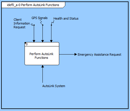
For the function:
 |
The standard IDEF0 diagram provides detailed view of ICOM within a function (essentially an "exploded" view of the A-0 context).Though related in concept, the representation differs and is implemented as a separate diagram in CORE. |
On the A-0 diagram, it is common to see tunneling. Tunneling is a technique within IDEF0 to hide an ICOM in part of the model. The use of parentheses around either the head or tail of an arrow depicts a tunnel in IDEF0. A parenthesis around the head of an arrow that is entering a function box indicates that the ICOM associated with that arrow will not be seen on the decomposition of that function. If the ICOM does reappear, it will have parentheses around its tail. CORE handles this issue automatically. To insert a tunnel, just remove the item on the child page, and then CORE automatically inserts a tunnel on the head of the arrow on the parent page.
An IDEF0 model should have a purpose and viewpoint. These are usually placed on the context page. In CORE these can be inserted by using the Insert Note command.
| |
A good reference for further information on the IDEF0 diagram is National Institute of Standards and Technology (NIST), Federal Information Processing Standards Publication 183 (FIPS PUB 183), Specification for Integration Definition for Function Modeling (IDEF0). |
In addition to the classic diagram options, the IDEF0 diagram settings include:
Show Box Numbers - controls whether or not to display IDEF0 box numbers in the lower-right corner of every icon.
Use DRE - controls whether a Detail Reference Expression (DRE) instead of a decomposition box in the upper right corner to represent that an additional layer of detail exists. If the DRE is used, the element number is displayed below the lower-right corner of the icon to indicate the number of the decomposition diagram for the element.
The constructs and key entities tabs allow you to quickly develop your IDEF0 diagram, while the all entities tab enables you to relate your functions, items, and components to the remainder of your system definition.
Constructs
New Input - drop onto any function node to create a new item as an input (inputs)
Inputs - drop onto any function node to add an existing item as an input (inputs)
New Control - drop onto any function node to create a new item as a control (triggers)
Controls - drop onto any function node to add an existing item as a control (triggers)
New Output - drop onto any function node to create a new item as an output (output from)
Outputs - drop onto any function node to add an existing item as an output (output from)
New Mechanism - drop onto any function node to create a new component as a mechanism (performs)
Mechanisms - drop onto any function node to assign an existing component as a mechanism (performs)
New Information Block - drop onto the diagram to insert an information block (a mini property sheet)
New Note - drop onto the diagram to insert a new note (descriptive text in a note icon)
New Shape - drop onto the diagram to insert a new shape (a rectangle, rounded rectangle, circle, or ellipse with text, if desired)
New Graphic - drop onto the diagram to insert a new picture
Key Entities
Component - drop an existing component onto a function node to assign the component as the mechanism (performs)
Item - drop an existing item onto a function node to relate it to the node using the input to, triggers, or output from relation
All Entities - all classes and elements in the system model, allowing you to drag any element on top of a diagram node to establish relationships with the balance of your system model
Insert
Edit ICOM
Open Element view submenu