 (available in CORE Spectrum)
(available in CORE Spectrum)The requirements diagram is a specific SysML hierarchy with its own graphical notation linking requirements to system elements that satisfy and/or verify the given requirement. The CORE implementation allows for a range of placement options and icon sizing to support the range of information classically shown on requirements diagrams. Part of the requirements representation set, hierarchy diagrams are available for requirements and documents.
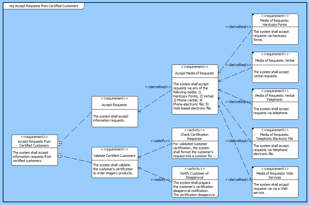
The requirements diagram uses a structured layout with specific movement rules for each node. However, multiple vertical and horizontal layouts are available, so select the one that best fits your specific style and the specific data set.
In a hierarchical format (which includes the requirements diagram), if the same element is encountered multiple times when traversing the database, it is shown on the diagram multiple times. This presents a clean representation and avoids "string art" of crossing lines. When an element appears in multiple places on the diagram, a small black square appears in the upper-right hand corner of the icon. In this event, CORE proceeds to expand the first occurrence of the element.
A node with a black square in the upper-left indicates that there is more information to display. This can occur if there are more relationships to traverse than the number of levels specified for the diagram. This can also occur if you collapse an existing node to hide the nodes beneath it. Individual nodes can be expanded or collapsed as desired to tailor the representation.
 |
A good reference for further information on requirements diagrams is chapter 13 of A Practical Guide to SysML: The Systems Modeling Language by Sanford Friedenthal, Alan Moore, and Rick Steiner (2012). |
In addition to the classic diagram options, the requirements diagram settings include:
Use Compact Placement - controls whether a compact placement algorithm is used when laying out the diagram.
Use Orthogonal Lines - controls whether orthogonal lines or direct lines are used to connect nodes on the diagram.
Layout - controls the default diagram layout to use with the diagram. Available diagram layouts options include vertical trees, horizontal trees, and more.
Levels - controls the initial number of levels to show on the diagram. Individual nodes can then be expanded or collapsed, as desired.
The constructs and key entities tabs allow you to quickly develop your requirements diagram, while the all entities tab enables you to relate your diagram elements to the remainder of your system definition.
Constructs
New Requirement - drop onto any diagram node to create a new derived requirement using the refined by relation
Requirements - drop onto any diagram node to add an existing requirement as a derived requirement using the refined by relation
New Block - drop onto any diagram node to create a new block (component) specified by the requirement node
Blocks - drop onto any diagram node to indicate that an existing block (component) is specified by the requirement node
New Activity- drop onto any diagram node to create a new activity (function) based on the requirement node
Activity - drop onto any diagram node to indicate that an existing activity (function) is based on the requirement node
New Verification Requirement - drop onto any diagram node to create a new verification requirement that verifies the requirement node
Verification Requirements - drop onto any diagram node to indicate that an existing verification requirement verifies the requirement node
New Information Block - drop onto the diagram to insert an information block (a mini property sheet)
New Note - drop onto the diagram to insert a new note (descriptive text in a note icon)
New Shape - drop onto the diagram to insert a new shape (a rectangle, rounded rectangle, circle, or ellipse with text, if desired)
New Graphic - drop onto the diagram to insert a new picture
Key Entities
Component - drop an existing component onto a node to establish any valid relationship. Most often, this will be the specifies relation.
Function - drop an existing function onto a node to establish any valid relationship. Most often, this will be the basis of relation.
Interface - drop an existing interface onto a node to establish any valid relationship. Most often, this will be the specifies relation.
Item - drop an existing item onto a node to establish any valid relationship. Most often, this will be the specifies relation.
Link - drop an existing link onto a node to establish any valid relationship. Most often, this will be the specifies relation.
Mode - drop an existing mode onto a node to establish any valid relationship. Most often, this will be the specifies relation.
Product - drop an existing product onto a node to establish any valid relationship. Most often, this will be the specifies relation.
ProgramActivity - drop an existing program activity onto a node to establish any valid relationship. Most often, this will be the basis of relation.
ProgramElement - drop an existing program element onto a node to establish any valid relationship. Most often, this will be the specifies relation.
Requirement - drop an existing requirement onto a node to establish any valid relationship. Most often, this will be parent-child (refines) or specification (specifies).
State - drop an existing state or mode onto a node to establish any valid relationship. Most often, this will be the specifies relation.
UseCase - drop an existing use case onto a node to establish any valid relationship. Most often, this will be the basis of relation.
VerificationRequirement - drop an existing verification requirement onto a node to establish the verified by relation.
All Entities - all classes and elements in the system model, allowing you to drag any element on top of a diagram node to establish relationships with the balance of your system model
Insert
Open Element view submenu