 (available in CORE Spectrum)
(available in CORE Spectrum)The sequence diagram captures the interaction between collaborating parts of a system. Part of the behavioral (logical architecture) representation set, the sequence diagram enables you to focus on triggering data and the resultant flow of control between components. This partial representation is particularly useful in understanding and confirming interactions early at each level of the system definition effort.
The sequence diagram is available for elements in the Function class (as well as any other subclasses of ProcessingUnit).
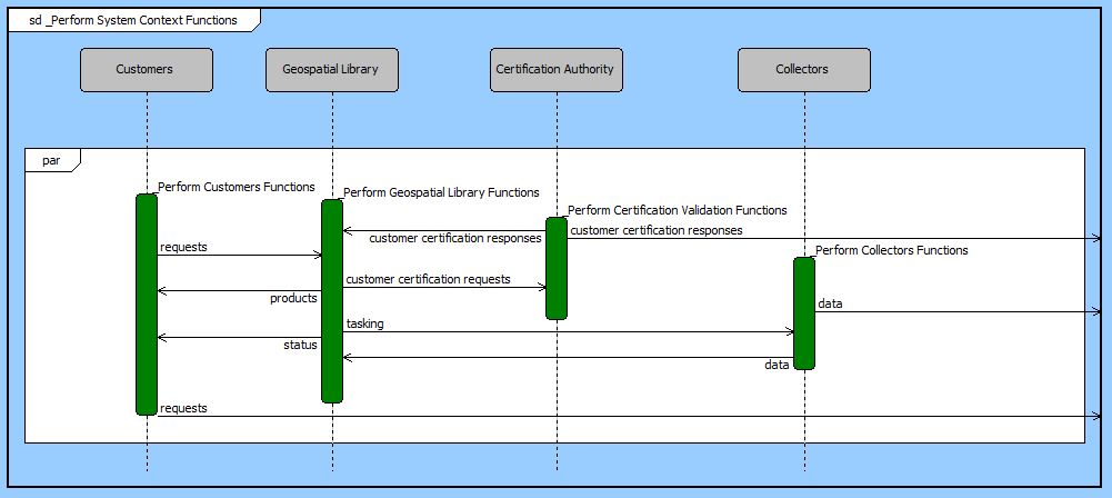
The sequence diagram displays the children in a function's decomposition along vertical lifelines. The individual child functions are identified by traversing the parent function's structure (best represented graphically by an activity diagram or an EFFBD). The allocation of these functions (the allocated to relationship) determines the collection of components displayed along the top of the diagram. Individual function nodes are then placed along the corresponding vertical lifeline with unallocated functions displayed on a special "unallocated" life line on the right side of the diagram.
The arrows on a sequence diagram represent control data, triggers that serve to synchronize interactions. An arrow entering the node triggers that function. An arrow exiting the node is an output that triggers another function. Arrows entering from the left edge of the diagram are external triggers that originate outside of this decomposition. Arrows that exit the right edge of the diagram are outputs that trigger functions elsewhere in the system model. Basic inputs (data stores) are not shown on the sequence diagram since the focus is on interactions.
CORE determines the order of functions on the sequence diagram by doing a static "execution" of the logic. In essence, the function's structure is traversed from start to finish. During this traversal, if the needed trigger for a function is already available, the function is placed in the next vertical position on the appropriate lifeline. If the trigger is not available, the function "waits" until it is available. This static "execution" does not have the dynamic rigor of executing the full model using the integrated COREsim engine, but it does ensure integrity and consistency between the sequence diagram and the underlying system model. The bottom line is that ordering of nodes on a sequence diagram cannot be manipulated directly via the sequence diagram (the representation is too ambiguous from this perspective, and changing the order would change the underlying model in ways unanticipated). The ordering is best managed by manipulating the activity diagram or EFFBD.
While the order is computed and you cannot position nodes out of order, you have great flexibility within those computational boundaries to lay the diagram out in a way that better communicates the interactions within your system.
Item arrows can be repositioned, either by grabbing and dragging the line or by grabbing the arrowhead.
The net result is a diagram that both represents the engineering truth of your system design and the visualization necessary to understand, analyze, and communicate.
 |
A good reference for further information on sequence diagrams is chapter 10 of A Practical Guide to SysML: The Systems Modeling Language by Sanford Friedenthal, Alan Moore, and Rick Steiner (2012). |
In addition to the classic diagram options, the sequence diagram settings include:
Show Function Names - controls whether function icons are labeled with their name. The emphasis on sequence diagrams is the interaction between components as represented by triggering items passing back and forth along the lifelines. Many times, the individual function identities are not critical, so toggling this option off can de-clutter the diagram. When shown, function names are displayed above the upper right corner of the function icon.
The constructs and key entities tabs allow you to quickly develop your interaction diagram, while the all entities tab enables you to relate your sequence diagram elements to the remainder of your system definition.
Constructs
New Node - drop onto the diagram background to create a new function as part of the diagram decomposition (decomposed by)
Nodes - drop onto the diagram background to add an existing function as part of the diagram decomposition (decomposed by)
New Trigger - drop onto any function node to create a new item that triggers the node
Triggers - drop onto any function node to relate an existing item that triggers the node
New Information Block - drop onto the diagram to insert an information block (a mini property sheet)
New Note - drop onto the diagram to insert a new note (descriptive text in a note icon)
New Shape - drop onto the diagram to insert a new shape (a rectangle, rounded rectangle, circle, or ellipse with text, if desired)
New Graphic - drop onto the diagram to insert a new picture
Key Entities
Component - drop an existing component onto a function node to allocate the function to the component.
Function - drop onto the diagram background to add an existing function as part of the diagram decomposition (decomposed by)
Item - drop an existing item onto a function node to establish any valid relationship. Most often, this will be triggers or output from.
All Entities - all classes and elements in the system model, allowing you to drag any element on top of a diagram node to establish relationships with the balance of your system model
Insert
Data
Open Element view submenu
While the sequence diagram can represent any portion of a system's logical model, the diagram is often at its best when illustrating and understanding system threads. When used in conjunction with integrated behavior, the sequence diagram can become a confused crossing of lines rather than a clear synchronization. If you choose to use the sequence diagram to represent an aspect of your integrated system behavior, consider hiding specific arrows that detract from the analytical and communication value.
The sequence diagram is frequently used with stakeholders and domain experts to ensure that the intended interactions have been captured and that the interactions between components are understood. Given this usage, the component nodes at the head of the lifelines are good candidates for using graphical images in place of geometric frames.
If your sequence diagram has a large number of arrows connecting to a single node (either output from or triggering the function), you may wish to elongate the one node by highlighting the node and dragging the bottom handle. This will provide more vertical space for arrows.
A parallel or concurrency construct is often referred to as a "don't care" construct since the developer is simply communicating that all of the branches must complete before the construct completes. However, the branch order does effect the static "execution" used to compute the order on the sequence diagram. Reordering branches on your activity diagram or EFFBD can greatly improve the layout on your sequence diagram.
Adjust the arrow label template, selectively changing what is displayed to better manage information content.