
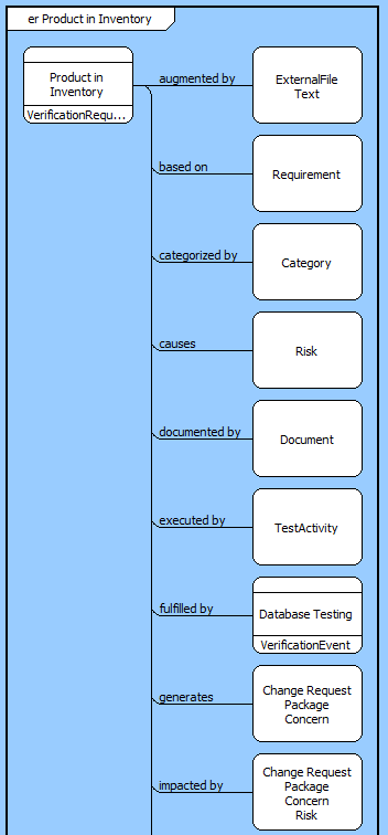
The ER diagram displays the relationships for a selected element in a graphical tree format. Part of the general representation set, this view provides a complete graphical picture of how a given element relates to other parts of your system definition. Optionally, it can also display other possible relations not yet defined for this element class.
The ER diagram represents a single level of relations. The icon on the left represents the element on which the diagram was opened. The icons along the right represent the targets related to the class. Each line connecting the element to a target is labeled with the name of the relationship that links the element to the targets. If the diagram is set to show all relations, relations without targets will be shown on the diagram with the possible target classes displayed in the node (a useful check for completeness). All relations are shown in alphabetical order. Within each relation, you can specify the appropriate sort block.
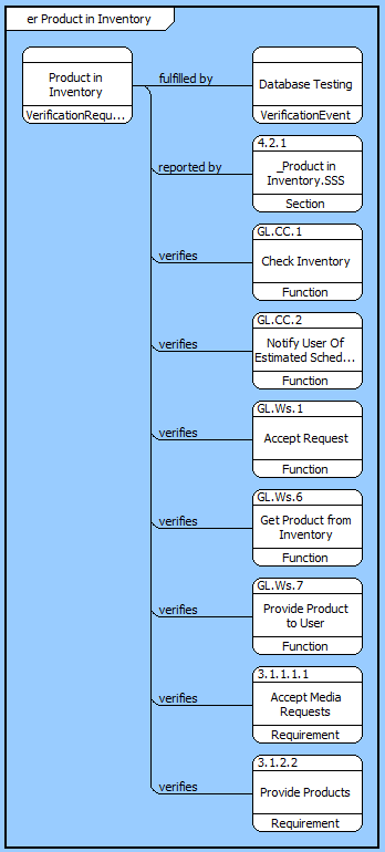
The ER diagram layout is structured. Target nodes can be moved down and right from their default position, but they cannot be moved up or left. The root node representing the class on which the diagram was opened can be moved anywhere on the diagram (though moving it to the right of the target nodes does not change the connection point for the relation lines).
 |
Relations have color profiles to define how those objects should be displayed on diagrams by default. By default, the font and line colors for traceability hierarchy relations (allocated to, basis of, causes, documents, generates, refined by, results in, and specifies) have been set to green. This color change helps highlight specific relations of interest (in the case of the default relations, this helps differentiate primary traceability). |
In addition to the classic diagram options, the ER diagram settings include:
Show All Relations - This setting controls whether all relations - including those relations without targets - should be shown on the diagram. If this option is toggled on, relations without targets will be shown on the diagram with the possible target classes displayed in the node. This is a useful check for completeness but can detract attention from the established relationships.
The constructs tab allows you to quickly decorate your ER diagram, while the all entities tab enables you to relate your diagram elements to the remainder of your system definition.
Constructs
New Information Block - drop onto the diagram to insert an information block (a mini property sheet)
New Note - drop onto the diagram to insert a new note (descriptive text in a note icon)
New Shape - drop onto the diagram to insert a new shape (a rectangle, rounded rectangle, circle, or ellipse with text, if desired)
New Graphic - drop onto the diagram to insert a new picture
All Entities - all classes and elements in the system model, allowing you to drag any element on top of a diagram node to establish relationships with the balance of your system model
Insert
Open Element view submenu