
The interface block diagram is a traditional systems engineering block-and-line diagram representing the logical interfaces that connect components within a system or system segment. Classically, whether working top-down, middle-out, or bottom-up, the logical connections are known long before the physical implementations of these connections are clear. Part of the physical architecture representation set, the interface block diagram is often the first architectural block diagram that you will develop, focusing first on the fact that logically A must interface with B before crossing into the details of how that connection is made.
The interface block diagram is available for elements in the Component class (as well as any other subclasses of ImplementationUnit).
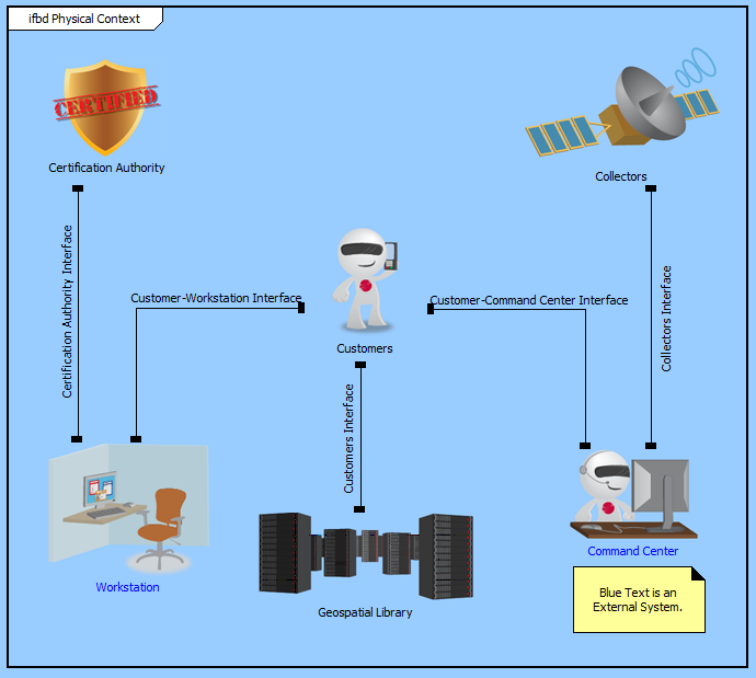
In this classic variant of a component wiring diagram, the children of the component are shown as nodes on the diagram. Lines connecting to a node reflect the interfaces joined to the node. If the interface does not connect to another component in the system model, the interface is drawn as an unterminated line (an obvious diagnostic for resolution). If the interface joins to two components within the decomposition, both ends of the line are connected to classic nodes. If one end of the interface exists outside the composition of this component (if the interface is an external interface), the external component is also shown on the diagram and joins to the interface to show the full context. To help distinguish external components which interface to subcomponents from the subcomponents themselves, external components are drawn with a grey background by default.
If you are using a legacy schema (pre v90), CORE displays implied and "rolled up" relationships as well (this was discontinued in CORE 9 in favor of decomposable interfaces). When component A joins to an interface that joins to a child of component B, there is an implied interface with component B itself. Likewise, when an interface is defined lower in the composition tree and it joins external to the composition tree (it connects to a subcomponent that is not built in this tree), there is an implied interface at higher levels. As you define your physical composition and your interfaces, CORE automatically computes these implied interfaces and represents them using the joins thru relationship. To present a complete picture of declared and implied interfaces, the interface block diagram displays both.
 |
CORE implements a second variant of the interface block diagram - a level 0 (L0) interface block diagram - to focus exclusively on the current design level without considering implied or "rolled up" interfaces. If you are using a v90 schema, the level 0 and the interface block diagram are equivalent. |
The interface block diagram is a free-form diagram. CORE begins with a simple diagonal layout for the nodes, but you can customize node positions as desired. Individual lines can be repositioned as well. Drag the handle at the connection point with the node to control where the line connects to the node. Drag a handle at a bend in the line to move that line segment. Individual labels can be rotated and moved. When the label separates too far from the connection line, a "lightning bolt" will draw to automatically connect the label its corresponding line.
| |
The CORE schema limits an interface to join a maximum of two components. While we typically think of an interface connecting multiple nodes, a better image of an interface is a logical plane between two components. In a hub or bus model, the hub or bus itself is in reality a component. In other models where interfaces share common characteristics, it is generally the interface specification which is common. The interfaces themselves are unique to the specific pairs of components. |
The interface block diagram settings do not include any special diagram options beyond the classic diagram options.
The constructs and key entities tabs allow you to quickly develop your interface block diagram, while the all entities tab enables you to relate your components and interfaces to the remainder of your system definition.
Constructs
New Node - drop onto the diagram background to add a new component as part of the diagram composition (built from)
Nodes - drop onto the diagram background to add an existing component as part of the diagram composition (built from)
New Connection - drop onto any diagram node to create a new connection (interface) that joins to the node
Connections - drop onto any diagram node to relate an existing connection (interface) using the joins to relation
New Information Block - drop onto the diagram to insert an information block (a mini property sheet)
New Note - drop onto the diagram to insert a new note (descriptive text in a note icon)
New Shape - drop onto the diagram to insert a new shape (a rectangle, rounded rectangle, circle, or ellipse with text, if desired)
New Graphic - drop onto the diagram to insert a new picture
Key Entities
Component - drop an existing component onto the diagram background to add it as part of the diagram composition (built from)
Interface - drop an existing interface onto a node to relate it to the node using the joins to relation
All Entities - all classes and elements in the system model, allowing you to drag any element on top of a diagram node to establish relationships with the balance of your system model
Insert
Open Element view submenu