 (available in CORE Spectrum)
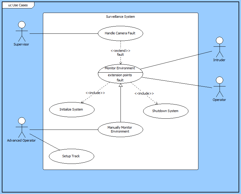
(available in CORE Spectrum)Use cases describe the functionality of a system from the user perspective. The use case diagram is a graphical representation of actors (humans), blocks (components), and use cases.
Use cases are effectively the names of MBSE threads, capturing concepts and context that should be translated into threads and the integrated system logic. They are often used as elicitation and discovery tools, helping to better understand the system under consideration and transition from requirements and operational context to behavioral threads. The conceptual modeling flow (in top-down design) begins with the requirements. From the requirements, you define the system boundary – physical and functional – and identify the context. From this context and the operational concept that drives it, use cases are identified. Use cases are then elaborated by functional threads which provide the insight needed to develop the integrated logic. A view of how use cases fit into the greater language of MBSE is shown below.

Note that this is not the only flow nor is it the prescribed flow. For example, use cases can be tied to requirements. They can also exist free-floating. However, the conceptual flow places use cases into the overall context of the MBSE model. They serve to make the development of threads more disciplined, explicit, and rich. At any layer of development, you can identify the threads that influenced the development of the integrated logic by
For the use case diagram
The use case diagram is a free-form diagram. CORE defaults to specific layout behaviors, but you are free to rearrange content within the bounds of certain constraints:
 |
A good reference for further information on use case diagrams is chapter 12 of A Practical Guide to SysML: The Systems Modeling Language by Sanford Friedenthal, Alan Moore, and Rick Steiner (2012). |
In addition to the classic diagram options, the use case diagram settings include:
Use Stick Figures - determines whether human actors are drawn as stick figures. By default, components of type human are drawn as stick figures with the name displayed below. All other component types are drawn as rectangles with a corresponding icon template defining the content. If this option is toggled off, all component types will be drawn as rectangles.
The constructs and key entities tabs allow you to quickly develop your use case model, while the all entities tab enables you to relate your use case model to the remainder of your system definition.
Constructs
New Use Case - drop onto any diagram node to create a new block (component) as part of the node composition (built from)
Use Cases - drop onto any diagram node to relate an existing block (component) as part of the node composition (built from)
New Actor - drop onto any diagram node to create a new block (component) as part of the node composition (built from)
Actors - drop onto any diagram node to relate an existing block (component) as part of the node composition (built from)
New Information Block - drop onto the diagram to insert an information block (a mini property sheet)
New Note - drop onto the diagram to insert a new note (descriptive text in a note icon)
New Shape - drop onto the diagram to insert a new shape (a rectangle, rounded rectangle, circle, or ellipse with text, if desired)
New Graphic - drop onto the diagram to insert a new picture
Key Entities
Component - drop an existing component onto a node to establish any valid relationship. Most often, this will be composition (built from).
UseCase - drop an existing component onto a node to establish any valid relationship. Most often, this will be composition (built from).
All Entities - all classes and elements in the system model, allowing you to drag any element on top of a diagram node to establish relationships with the balance of your system model
Insert
Open Element view submenu