 (available in CORE Spectrum)
(available in CORE Spectrum)Whereas a block definition diagram (BDD) is used to define blocks in terms of their features and structural representations, the IBD shows the connections between parts of a block. The IBD is similar to traditional system block diagrams. Part of the physical architecture representation set, there are two primary variants of the IBD:
Given the clear distinction in characteristics and usage of these two variants, they have been implemented as two separate diagrams in CORE.
The IBD is available for elements in the Component class (as well as any other subclasses of ImplementationUnit).
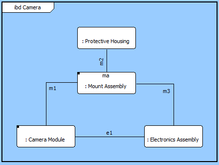
In this variant of a component wiring diagram, the children of the component are shown as nodes on the diagram. Lines connecting to a node reflect the interfaces joined to the node. If the interface does not connect to another component in the system model, the interface is drawn as an unterminated line (an obvious diagnostic for resolution). If the interface joins to two components within the decomposition, both ends of the line are connected to classic nodes. If one end of the interface exists outside the composition of this component (if the interface is an external interface), the connection is drawn to the boundary of the diagram.
 |
The CORE schema limits an interface to join a maximum of two components. While we typically think of an interface connecting multiple nodes, a better image of an interface is a logical plane between two components. In a hub or bus model, the hub or bus itself is in reality a component. In other models where interfaces share common characteristics, it is generally the interface specification which is common. The interfaces themselves are unique to the specific pairs of components. |
The content and underlying model mappings for the standard IBD are equivalent to the level 0 interface block diagram. The differences in moving between the SysML diagram and its traditional counterpart are:
The IBD is a free-form diagram. CORE begins with a simple diagonal layout for the nodes, but you can customize node positions as desired. Individual lines can be repositioned as well. Drag the handle at the connection point with the node to control where the line connects to the node. Drag a handle at a bend in the line to move that line segment. Individual labels can be rotated and moved. When the label separates too far from the connection line, a "lightning bolt" will draw to automatically connect the label its corresponding line.
| |
A good reference for further information on IBDs is chapter 7 of A Practical Guide to SysML: The Systems Modeling Language by Sanford Friedenthal, Alan Moore, and Rick Steiner (2012). |
In addition to the classic diagram options, the IBD settings include:
Show Ports - controls whether the ports at which the connections connect to the component are shown. If enabled, an open square is drawn at the intersection of the connection and the node. If a port name has been specified (as an attribute on the connecting relationship), the port name is displayed adjacent to the port. In addition, in the case of the flow IBD, the port shows the directionality that has been specified (as an attribute on the connecting relationship).
The constructs and key entities tabs allow you to quickly develop your IBD, while the all entities tab enables you to relate your components and interfaces to the remainder of your system definition.
Constructs
New Node - drop onto the diagram background to create a new block (component) as part of the node composition (built from)
Nodes - drop onto the diagram background to add an existing block (component) as part of the node composition (built from)
New Connection - drop onto any diagram node to create a new connection (interface) that joins to the node
Connections - drop onto any diagram node to relate an existing connection (interface) using the joins to relation
New Information Block - drop onto the diagram to insert an information block (a mini property sheet)
New Note - drop onto the diagram to insert a new note (descriptive text in a note icon)
New Shape - drop onto the diagram to insert a new shape (a rectangle, rounded rectangle, circle, or ellipse with text, if desired)
New Graphic - drop onto the diagram to insert a new picture
Key Entities
Component - drop an existing component onto a node to establish any valid relationship. Most often, this will be composition (built from)
Interface - drop onto any diagram node to relate an existing connection (interface) using the joins to relation
All Entities - all classes and elements in the system model, allowing you to drag any element on top of a diagram node to establish relationships with the balance of your system model
Insert
Open Element view submenu