 (available in CORE Spectrum)
(available in CORE Spectrum)The flow IBD is a SysML block-and-line diagram representing the physical links that connect components (and optionally the items that they carry) within a system or system segment. Part of the physical architecture representation set, the flow internal block diagram is the most detailed view of the architecture composition.
The flow internal block diagram is available for elements in the Component class (as well as any other subclasses of ImplementationUnit).
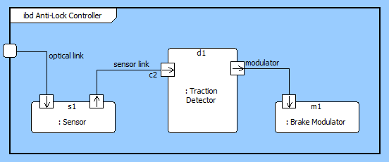
In this variant of a component wiring diagram, the children of the component are shown as nodes on the diagram. Lines connecting to a node reflect the links (the physical connections) connected to the node. If the link does not connect to another component in the system model, the connection is drawn as an unterminated line (an obvious diagnostic for resolution). If the link connects to two components within the decomposition, both ends of the line are connected to classic nodes. If one end of the link exists outside the composition of this component (if the link is an external connection), the connection is drawn to the boundary of the diagram.
 |
CORE implements a second variant of the IBD - a standard IBD - to focus on the logical interfaces between components as opposed to the physical connections. The standard IBD is classically developed before the flow IBD since the logical connection between two components is known before the physical implementation of the connection is developed. |
The content and underlying model mappings for the standard IBD are equivalent to the level 0 physical block diagram. The differences in moving between the SysML diagram and its traditional counterpart are:
External nodes are not represented on the IBD. If a part is connected to an external node, a connection is drawn to the boundary of the diagram.
Connections are labeled with the name of the link. Optionally, item flows can be displayed as well. CORE determines this by querying the transfers relationship of the link to obtain the collection of items. These are shown in curly brackets after the link name.
Ports can optionally be displayed. If displayed, a square is drawn at the intersection of the connection and the node. The port displays the directionality of the connection – in, out, or inout – as specified on the connected to relationship. If a port name has been specified (as an attribute on the connected to relationship), the port name is displayed adjacent to the port.
The flow IBD is a free-form diagram. CORE begins with a simple diagonal layout for the nodes, but you can customize node positions as desired. Individual lines can be repositioned as well. Drag the handle at the connection point with the node to control where the line connects to the node. Drag a handle at a bend in the line to move that line segment. Individual labels can be rotated and moved. When the label separates too far from the connection line, a "lightning bolt" will draw to automatically connect the label its corresponding line.
| |
A good reference for further information on IBDs is chapter 7 of A Practical Guide to SysML: The Systems Modeling Language by Sanford Friedenthal, Alan Moore, and Rick Steiner (2012). |
In addition to the classic diagram options, the IBD settings include:
Show Ports - controls whether the ports at which the connections connect to the component are shown. If enabled, an open square is drawn at the intersection of the connection and the node. If a port name has been specified (as an attribute on the connecting relationship), the port name is displayed adjacent to the port. In addition, in the case of the flow IBD, the port shows the directionality that has been specified (as an attribute on the connecting relationship).
Show Item Flow - controls whether the items transferred by connecting links are shown on flow IBDs. If enabled, item names are shown in braces as part of the connection label.
The constructs and key entities tabs allow you to quickly develop your flow IBD, while the all entities tab enables you to relate your components and links to the remainder of your system definition.
Constructs
New Node - drop onto the diagram background to create a new block (component) as part of the node composition (built from)
Nodes - drop onto the diagram background to add an existing block (component) as part of the node composition (built from)
New Connection - drop onto any diagram node to create a new connection (link) that connects to the node
Connections - drop onto any diagram node to relate an existing connection (link) using the connects to relation
New Information Block - drop onto the diagram to insert an information block (a mini property sheet)
New Note - drop onto the diagram to insert a new note (descriptive text in a note icon)
New Shape - drop onto the diagram to insert a new shape (a rectangle, rounded rectangle, circle, or ellipse with text, if desired)
New Graphic - drop onto the diagram to insert a new picture
Key Entities
Component - drop an existing component onto a node to establish any valid relationship. Most often, this will be composition (built from)
Link - drop onto any diagram node to relate an existing connection (link) using the connects to relation
All Entities - all classes and elements in the system model, allowing you to drag any element on top of a diagram node to establish relationships with the balance of your system model
Insert
Open Element view submenu