Property Sheet
Property sheets, displayed on the right side of the GENESYS window when an item is selected in Project Explorer, represent an entity in a classic, textual format. This includes the attributes, properties, parameters, diagnostics, relationships, and targets of those relationships, and any attributes on those relationships. Attributes are displayed in the upper portion of the window in labeled text panes. The possible relations and assigned targets of those relations that complete the entity definition are displayed in the lower portion of the window.
Attributes
Each class of entity in GENESYS has a specific set of attributes which provide detail, depth, and richness for entities in GENESYS. The attributes are defined as part of the schema (the project metadata) and can be extended and tailored by the project team. Some attributes are common across all classes (description and number, for example). Others are defined just for a given class (the origin attribute for a requirement, for example).
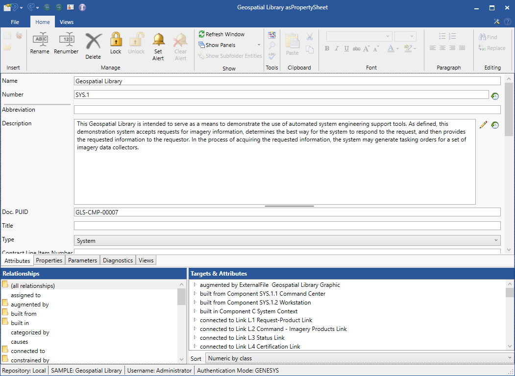
The upper region of the property sheet displays the attributes for the given entity in a classic form. Each attribute field has a label and a corresponding field for editing the attribute value. The specific layout of the field differs based upon the type of the attribute - a single line field for a string, a multi-line field for text, a drop-down field for an enumeration (pick list), etc. If an attribute is read-only or if you don't have permission to change an attribute, the field background will be gray. If you don't have read permission to an attribute, the field will be blank.
If versioning is enabled (at the project level) and an attribute has been marked to maintain versions (at the class level in the schema), the value field will be followed by a small button ![]() . This allows you to browse past versions of this attribute, compare two values side-by-side, and restore a past value, if desired.
. This allows you to browse past versions of this attribute, compare two values side-by-side, and restore a past value, if desired.
Commands that are available in the attribute fields include (where appropriate):
- Cut
- Copy
- Paste
- Paste Unformatted (text fields only)
- Clear All Formatting (text fields only)
- Report Options (text fields only)
- Insert Parameter (text fields only)
Properties
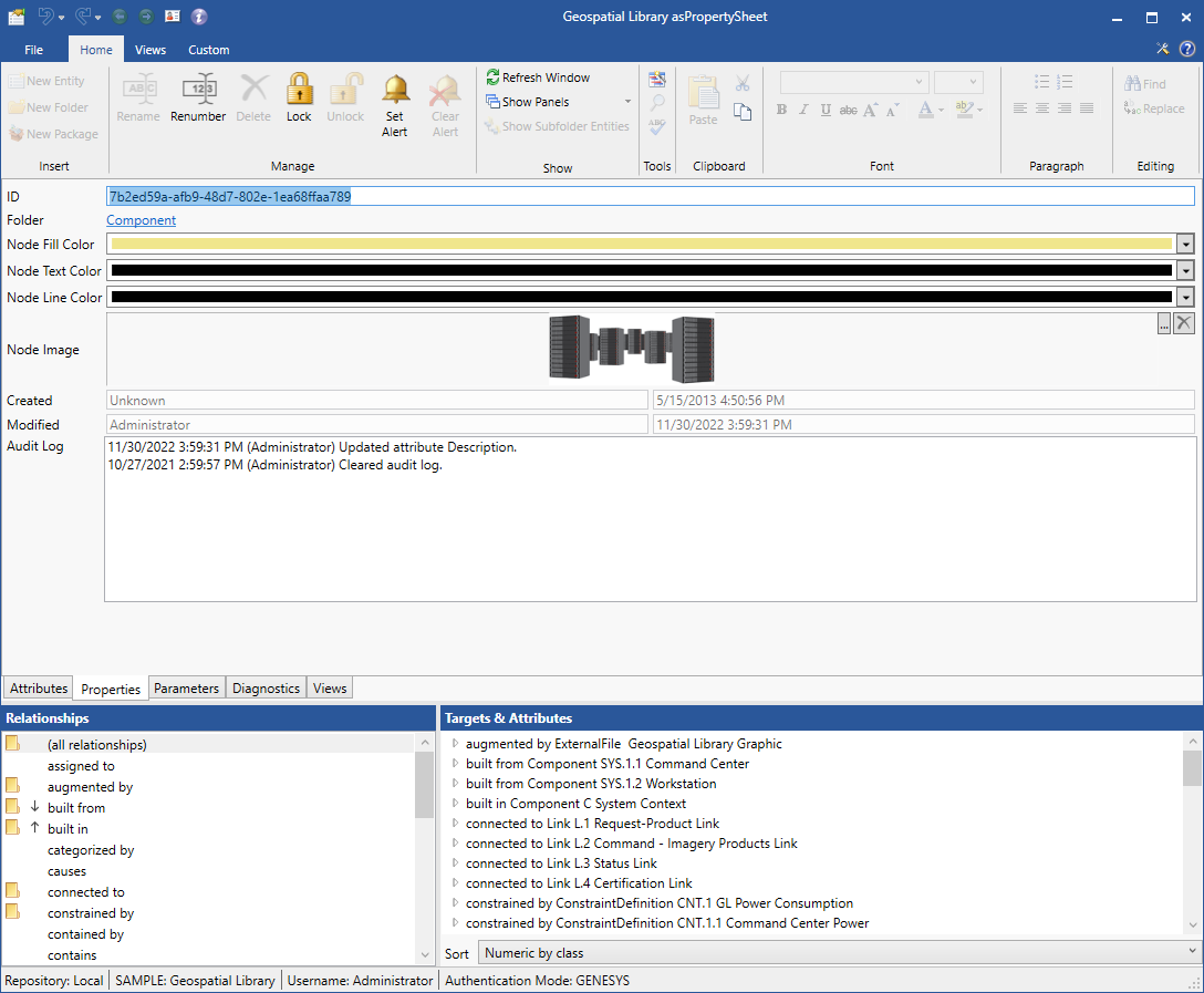
Each entity in GENESYS has a set of properties that are standard.
The Properties tab displays the same information for each entity:
- ID - the unique ID assigned to this entity. While the entity name is what people frequently use to reference entities, the unique ID is the underlying identity in GENESYS.
- Folder - the folder where this entity can be found. This is a hyper-link and will open a new project explorer with the folder and entity selected.
- Node Fill Color - default fill color for this entity wherever it appears on a diagram. This can be overridden on a diagram-by-diagram basis, but color can be used to draw attention to any desired aspect (important concerns, functions performed by humans, etc.).
- Node Text Color - default text color for this entity wherever it appears on a diagram. This can be overridden on a diagram-by-diagram basis, but color can be used to draw attention to any desired aspect (important concerns, functions performed by humans, etc.).
- Node Line Color - default line color for this entity wherever it appears on a diagram. This can be overridden on a diagram-by-diagram basis, but color can be used to draw attention to any desired aspect (important concerns, functions performed by humans, etc.).
- Node Image - an image that can be used to represent this entity on diagrams in place of traditional boxes and geometric frames. The default image comes from the class image set in the schema. Use the Set Image command to select a different image to represent the entity on diagrams.
- Created - the user name and time stamp when this entity was created.
- Modified - the user name and time stamp when this entity was las t changed.
- Audit Log - a basic textual log of all changes made along with the timestamp and the responsible user. Combined with the highly detailed attribute versioning and the project comparison reports, audit logs provide insight into the evolution of an entity when enabled at the project level.
Parameters
The Parameters tab provides access to all design parameters which have been defined for this entity. Parameters enable the project team to expose critical design-dependent and design-independent values for management and manipulation while seamlessly embedding them in text attributes for the convenience of natural language. Parameters may be predefined by the Project Administrator or may be user-defined at "runtime" whenever a project team member decides that a new value should be independently tagged and managed. Unlike attributes which are instantiated for every entity in a class, parameters are only instantiated on specific entities so each entity in a class may have a different set of parameters.
As critical design aspects, versioning is always enabled for parameters (when versioning is enabled for a project).
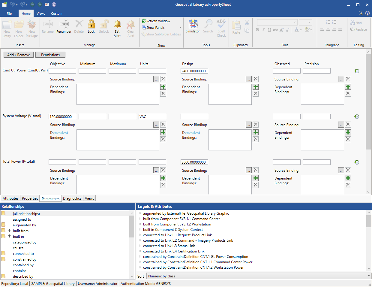
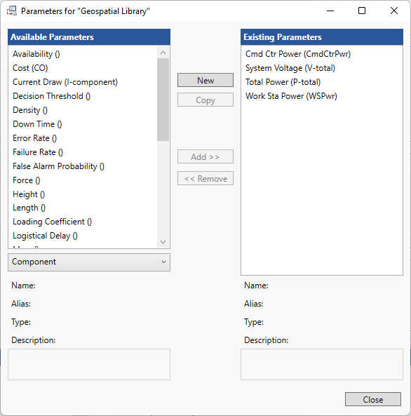
The Add / Remove buttons enable you to add a new parameter or remove an existing parameter, respectively, from this entity. You have the option of selecting a parameter definition that has already been established for this class or creating a new parameter on the fly. You can also create a parameter directly from any entity text attribute (such as description) by using the Insert Parameter command.
The Permissions button enables you to set parameter permissions. If a user does not have read permission to a parameter, they will see that a parameter is defined, but they will be unable to access the value.
Diagnostics
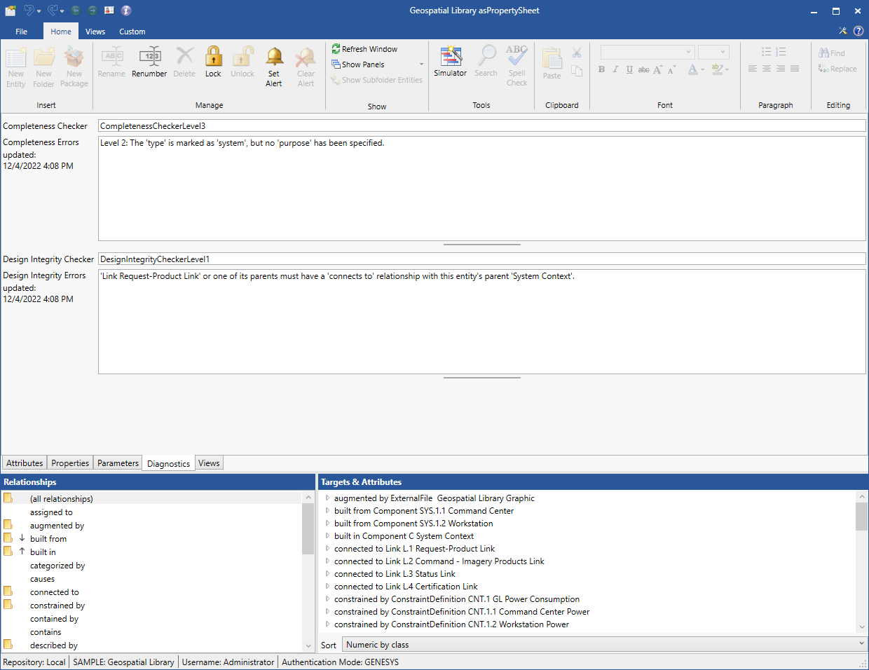
GENESYS includes a rich framework of embedded static model diagnostics to complement the dynamic validation provided by a simulator. With a library of over 70 completeness checks, countless consistency diagnostics, and a customizable framework for including your own rules, these model diagnostics go far beyond simple diagram-centric checks. The results of these checks are shown on the diagnostics tab. These diagnostics aid in the bookkeeping and validation of systems engineering, freeing you to focus your valuable time on the critical inspiration of systems engineering.
- Completeness Checker - descriptive string for the current completeness check rules in use for this project. A project administrator defines this using the Select Completeness Checker command. Not all rules are valid on day one of your project. As your design matures, your completeness checks should become more sophisticated and robust. With this in mind, for each project you specify one of three levels of completeness checks from none to rich tuning to your specific needs.
- Completeness Errors - a list of the database completeness rules that have failed informing you which key attributes and relationships have not yet been completed. The completeness errors will automatically be updated every time this tab is selected, ensuring that the latest status is shown.
- Updated (completeness errors) - a timestamp reflecting the last time the completeness errors were updated.
- Design Integrity Checker - descriptive string for the current design integrity check rules in use for this project. A Project Administrator defines this using the Select Design Integrity Checker command. Not all rules are valid on day one of your project.
- Design Integrity Errors - a list of the design integrity errors that have been reported. Project properties include the definition of a design integrity script to implement design integrity tests (horizontally across the model and vertically across decomposition of the model). The design integrity rules are a pre-defined (and extensible) set of rules to highlight inconsistencies in the model as you work across the systems engineering domains or across levels of detail.
- Updated (design integrity errors) - a timestamp reflecting the last time the design integrity errors were updated.
Views
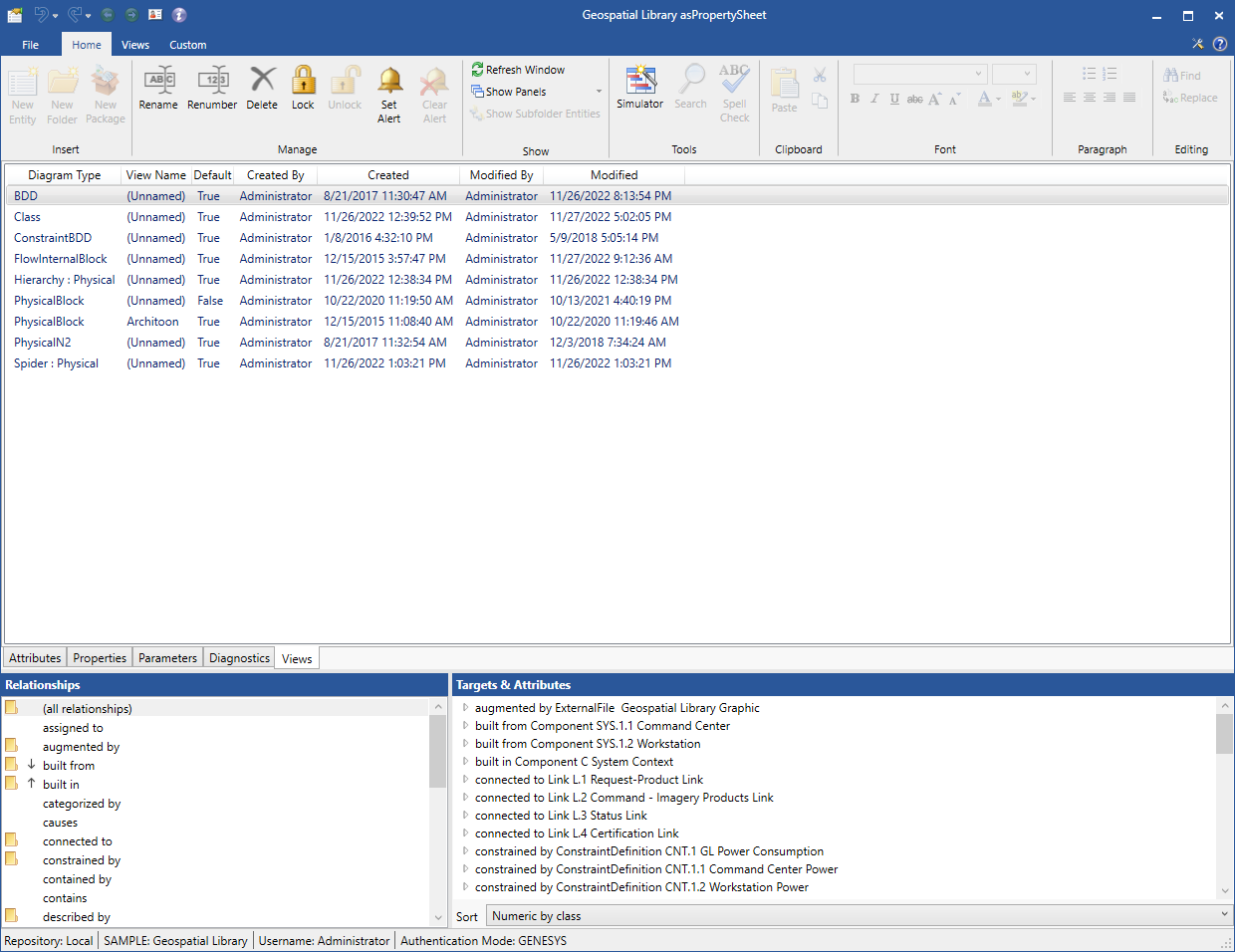
Each entity can have multiple saved views. These are listed in a table format on the property sheet for the entity under the Views tab in the middle of the property sheet. All saved views for the entity are listed. This does not mean that you cannot open a diagram not listed here - you will simply get the default layout with the appropriate data from the database. To do this, use the Views tab at the top of the page to open the diagram.
Commands that are available on a selected view:
Relationships
Just as each class of entity has a specific set of attributes which provide greater detail, each class has a collection of relationships that bring meaning and context to the system model. The available relationships and their corresponding target classes are defined as part of the schema (the project metadata) and can be extended and tailored by the project team.

The valid relationships for the entity's class are shown in the relationships pane. Those relationships with targets defined are marked with a folder icon. Relationships without any current targets are shown without any marking.
Selecting a relationship from the relationships pane displays the corresponding targets in the Targets & Attributes pane. If the relationship has been defined to include attributes (for example the amount of a resource consumed by a function or the flow direction on a connection port), the relationship attributes are shown as well. To create a relationship, double-click on the relationship or use the Edit Targets command to open the target window.
The targets are sorted and displayed according to the selected sort block for the selected relation. You can select a different sort block to sort the target list by selecting from the drop-down list. When using the (all relationships) entry to see all relationships for the entity, the relationships are sorted first by the relationship and then by the specified sort block.
Tips and Tricks
- At any time from virtually any screen in GENESYS, double-clicking on an entity is a shortcut for opening the property sheet.
- Use the tab key to quickly move through and populate fields on your entity property sheet.
- The property sheet includes sizing bars (split bars) to control the relative size of the different window portions. A sizing bar between the attribute labels and value panes allows you to resize to show the complete attribute label, where desired. The sizing bar between the attribute fields at the top of a property sheet and the relationships list at the bottom of the window should be used frequently. When focused on the properties of the entity (authoring a description, etc), you will want more space for the attributes. When you are reviewing how the entity connects to the rest of your system model, you will want more space for the relationships.
- The all relationships selection in the relations list pane provides a compact textual representation of how the entity is connected to the rest of the system model. You can also remove relationships directly from this list.
