 (available in CORE Spectrum)
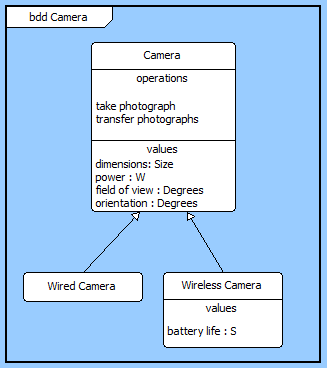
(available in CORE Spectrum)The classification BDD represents the inheritance structure of systems, components, items, conceptual entities, and logical abstractions. Part of the physical architecture representation set, this diagram represents the classification structure (superclasses and subclasses) of a model. This is the systems variant of the UML class diagram. Rather than representing the structure of an implementation unit, it represents the inheritance tree (for example, TransportationEntities is a generalization of Planes, Trains, and Automobiles).
The classification BDD is available for elements in the Component class (as well as any other subclasses of ImplementationUnit).
The BDD uses a structured layout with specific movement rules for each node. However, multiple vertical and horizontal layouts are available, so select the one that best fits your specific style and the specific data set.
 |
CORE implements a second variant of the block definition diagram - a structure BDD - to represent the structure / composition of an implementation unit. |
Multiple node representations are supported by block diagrams. In addition to the element name, you will frequently see some combination of the following fields:
One decoration of the block definition diagram are not currently represented on CORE's BDDs, specifically identification of reference properties (where a component is "in, but not of" the enclosing block)
| |
A good reference for further information on BDDs is chapter 7 of A Practical Guide to SysML: The Systems Modeling Language by Sanford Friedenthal, Alan Moore, and Rick Steiner (2012). |
In addition to the classic diagram options, the BDD settings include:
Use Compact Placement - controls whether a compact placement algorithm is used when laying out the diagram.
Use Orthogonal Lines - controls whether orthogonal lines or direct lines are used to connect nodes on the diagram.
Show Role Names - controls whether the part role for the node is shown on the diagram.
Layout - controls the default diagram layout to use with the diagram. Available diagram layouts options include vertical trees, horizontal trees, and more.
Levels - controls the initial number of levels to show on the diagram. Individual nodes can then be expanded or collapsed, as desired.
The constructs and key entities tabs allow you to quickly develop your block definition, while the all entities tab enables you to relate your blocks to the remainder of your system definition.
Constructs
New Node - drop onto any diagram node to create a new block (component) inherited from the node (generalization of)
Nodes - drop onto any diagram node to relate an existing block (component) inherited from the node (generalization of)
New Information Block - drop onto the diagram to insert an information block (a mini property sheet)
New Note - drop onto the diagram to insert a new note (descriptive text in a note icon)
New Shape - drop onto the diagram to insert a new shape (a rectangle, rounded rectangle, circle, or ellipse with text, if desired)
New Graphic - drop onto the diagram to insert a new picture
Key Entities
Component - drop an existing component onto a node to establish any valid relationship; most often, this will be inheritance (generalization of)
All Entities - all classes and elements in the system model, allowing you to drag any element on top of a diagram node to establish relationships with the balance of your system model
Insert
Open Element view submenu
To communicate the full technical depth of the block structure, block definition diagrams classically include far more content per node than other diagrams. Make liberal use of the ability to specify different icon templates for each node, using more complete templates where operations/values/ports are desired and lesser templates where they are not. Not only does this tighten the diagram, it helps focus attention on the critical aspects you are seeking to emphasize.