Building and Manipulating Diagrams
GENESYS's many diagrams can be accessed in multiple ways. When using the entity browser pane in the project explorer, the first thing you will note when selecting a class is the most common set of representations associated with that type of entity are represented as tabbed views along the bottom of the browser pane. This reinforces the integrated nature of the system model and the fact that individual representations are truly projections that allow you to better understand and manipulate the underlying model. As you select individual entities, you can click through and access the various views within the tabs. You can also use the Views ribbon or the Open Entity context menu command to open views in separate windows.
|
NOTE: |
The tabbed views in Project Explorer enable you to quickly move between views and entities without cluttering your screen with multiple windows. Opening views in separate windows allows you to maximize the screen space for a given representation or see multiple perspectives at once. Experienced users frequently leverage both approaches to maximize their effectiveness. |
Each specific diagram in GENESYS has been tailored to use custom commands to speed development and understanding using the native terminology for that particular representation. However, whether accessed via the project explorer tabs or opened in a separate window, all GENESYS diagrams share several common aspects - the diagram, the toolbox, and the ribbons.
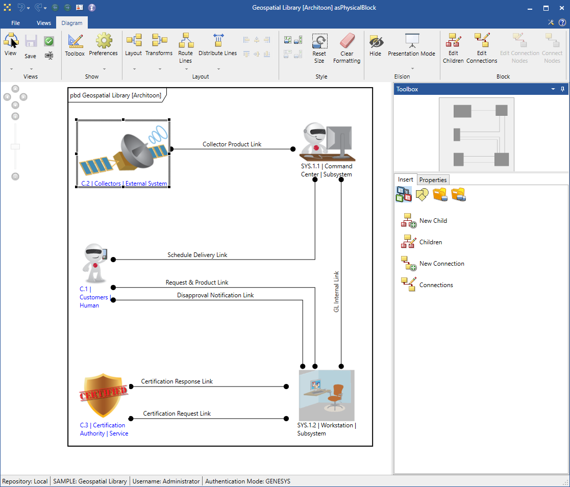
The Diagram Itself
Diagrams graphically communicate the interrelationships of the underlying system model. They provide customized graphical views communicating richness that cannot be clearly communicated through basic text statements. They can provide rich context or narrow focus.
Every GENESYS diagram consists of a collection of nodes and connecting lines. The individual nodes might be requirements in a hierarchy, functions on a behavior diagram, or components on an internal block diagram. Lines may represent relationships (traceability between a requirement and a system component) or entities themselves (a triggering item between two lifelines on a sequence diagram). In any event, the primary diagram pane is our canvas. As we manipulate the diagram content through menu commands or drag-drop, the diagram updates to reflect the current state of the system model.
The diagram pane follows very common paradigms:
- Select individual nodes (and lines and labels on some diagrams) by clicking on the node itself. Shift+click to select multiple objects. Click on the diagram background to clear all selections.
- Click on the diagram background and drag-select to select all objects within a region.
- Use the scroll bars or your mouse wheel to scroll to other parts of your diagram. When using your mouse wheel, hold down the shift key while scrolling (or tilt your wheel left and right) to scroll horizontally.
- Zoom in or out of your diagram using the scaling features. Hold down the control key and use your mouse wheel to scroll in and out to get the detail or context you need.
- Within a diagram, if you right-click and move the mouse, GENESYS will initiate a drag-drop operation for the current selection(s). Alternatively, if you hold down the control key and then left-click, GENESYS will initiate a drag-drop operation. Note that you can release the control key as soon as you left-click. You do not have to keep the control key depressed throughout the entire operation.
- If you right-click to drag, when you release the right mouse button, GENESYS will prompt you with a list of available operations move, copy, or link. The actual operations shown will change based upon the combination of objects being dragged and where you choose to drop them. GENESYS automatically determines the appropriate semantics and presents you with those choices.
- If you left-click to drag, the operation to be performed will change based upon the key combination you have depressed when you drop the object. If no keys are depressed, GENESYS will implement its default operation for the specific combination of objects. If the control key is depressed when you release the button, the operation is a copy. If the shift key is depressed, the operation is a link. In no circumstance will GENESYS present you with a choice that is not valid. If the GENESYS semantic for the drag-drop combination is limited to a link operation, holding the control key down will not allow you to copy.
- You may drag within a given pane (moving or relating content on the diagram), within a window (dragging content from the toolbox onto the diagram), or between windows (moving content or relating entities).
- Dragging onto an entity whether a functional node on an EFFBD, a connecting link on an internal block diagram, or an entity in a list is always interpreted as a link operation to create a relationship between the GENESYS entities. You will be presented with a dialog of all valid relationships, and the key relationships within the semantics of the diagram are shown in priority order with a blank space separating these from all other valid relationships. For example, if you drag an item onto a function node in a sequence diagram, the triggers relationship will be shown first in the list, the outputs relationship second, a blank space, and then the inputs relationship (valid for the entities involved but not impacting the sequence diagram).
Diagram Toolbox
Virtually anything you want to do to visually develop your system definition can be done via drag-drop. Drag an entity from a list onto a node to create a relationship. Drag two diagram nodes onto one another and have GENESYS guide you towards the relationships that make the most sense for the specific diagram. Drag a construct from a toolbox onto an activity branch to insert it. Repackage your system logic by dragging a construct from one branch to another or from one diagram to another.
While content can be dragged between windows, the toolbox along the right edge of the window is the most common tool when using drag-drop.

This toolbox can be hidden, closed, moved, and opened using the controls on the Toolbox or the Toolbox command on the ribbon, to ease model development or to maximize screen space . The toolbox contains the two tabs, Insert and Properties:
Insert
- Constructs - For those diagrams with defined semantics, the construct pane is populated with constructs specific to that diagram type. Dragging a construct onto a branch inserts the construct at the point you release it. Dragging a construct onto a node creates a relationship. As you drag, the cursor changes to show you if the construct can be dropped and the target emphasis highlights where the content will be inserted. For constructs that require additional information (what specific function you wish to insert, what domain set will be used, etc.), when you release the mouse to drop the construct, GENESYS will prompt you for the remaining information. (And if you want to insert based upon the traditional GENESYS rules, just double-click a construct on the toolbox.)
- Utilities - For all diagrams, the utilities pane provides a ready toolbox of diagram constructs to drag onto the diagram. At a minimum, the construct pane provides access to images, notes, and shapes to add richness to your diagram presentation and communication..
- Key Entities - Most diagrams focus on specific aspects of the model the physical composition and linkages on a physical block diagram; allocated functions, their triggers, and outputs on a sequence diagram; etc. To focus attention on these key classes and simplify navigation, the Key Entities tab shows just these classes. For example, on an internal block diagram, drag a component onto the background to add it to the physical decomposition. Drag an interface onto a diagram node to make the connection.
- All Entities - While each diagram focuses on specific model aspects, you are always looking at representations of the real underlying model. In many cases, you may want to create a relationship immediately even if it wont be shown on this particular view rather than flipping from view to view. For this reason, we have added the All Entities tab. Drag any entity onto a node, and GENESYS will prompt you with the possible ways to relate the two entities. Not only does this ease manipulation, it significantly lowers the learning curve on the language of MBSE.
Properties
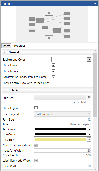
General Properties -
- Background Color - Select the background color for the diagram from the drop-down menu. The default is white but this can be set for each diagram type in the project by going to Project Preferences.
- Show Frame - The diagram frame contains information and bounds the diagram. At times this can be distracting so you are able to turn this off. To set what is shown in the diagram frame see the General section under Project Preferences.
- Show Inputs - Check this box to show inputs on the diagram.
- Constrain Boundary Items to Frame - Check this box to limit where boundary items can display to the frame.
- Show Control Flow with Dashed Lines - Check this box to display control flow in Activity diagrams with dashed lines.
Rule Set Properties -
- Rule Set - The rule set being used on the diagram. You can create and edit a Rule Set from the diagram toolbox by selecting Create or Edit under the Rule Set.
- Show Legend - Display a legend on the diagram that defines the Rule Set.
- Dock Legend - Dock the legend on the diagram.
- Font Size - The font size of the legend
- Title - Display a title on the legend
- Text Color -Text color on the legend
- Line Color - Line color on the legend
- Fill Color - Fill color of the legend
- Node/Line Proportional - Set the nodes and lines on the legend as proportional.
- Node/Line Width - Set the node and line width on the legend.
- Node Height - Set the node height on the legend.
- Label Use Node Width -Use the node width for the width of the label.
- Label Width -Width of the labels on the legend
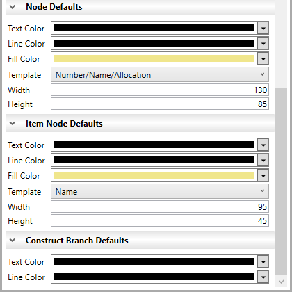
Node Defaults Properties -
- Text Color - Text color of the nodes on the diagram
- Line Color - Line color on the diagram
- Fill Color - Fill color of the nodes on the diagram
- Template - Template used for the nodes
- Width - Width of the nodes on the diagram
- Height - Height of the nodes on the diagram
Item Node Defaults Properties -
- Text Color - Text color for a selected node that overrides the default node settings
- Line Color - Line color for a selected node that overrides the default node settings
- Fill Color - Fill color for a selected node that overrides the default node settings
- Template - Template used for a selected node that overrides the default node template
- Width - Width of a selected node that overrides the default node width
- Height - Height of a selected node that overrides the default node height
Construct Branch Defaults Properties -
- Text Color - Text color of the construct branch
- LIne Color - Line color of the construct branch
Actions for All Diagrams Can be Undone/Redone
Actions for all diagrams can be undone and redone by selecting the Undo![]() and Redo
and Redo![]() icons, respectively, on the top left corner of the Diagram window. This saves a lot of time fixing diagrams.
icons, respectively, on the top left corner of the Diagram window. This saves a lot of time fixing diagrams.
Any action that changes the state of the diagram can be undone and redone. This includes layout changes like changing colors and sizes of nodes and moving items on the diagram. It also includes database transactions like creating and deleting entities, relationships, and attributes on the diagrams.
Nested ports can also be undone/redone on Flow IBD diagrams.
Prompt for Entity Names on Insertion
In User Preferences, there is an option Prompt for Entity Names on Insertion. By default, this option is enabled, when you drop a New ABC construct, you will be prompted to fill in the name before the entity is created. If you disable this option, dragging a New ABC construct onto the diagram will create a new entity with a default name. Sometimes, you want the best of both worlds quick entity creation for some drag-drop actions with the opportunity to fill out names for others. Holding down the CTRL key when dropping a New ABC construct onto a diagram will prompt you for the entity name regardless of the User Preference setting.
Establish Relationships
Note that you often think of dragging objects from the toolbox onto the diagram, you can also drag objects from the diagram onto toolbox entities to establish relationships. This is particularly useful when allocating functions on an activity diagram or connecting multiple nodes on an EFFBD, N2, or block diagram. Shift+click to select the entities of interest and then drop them onto the desired entity on the All Entities tab.
Diagram Ribbon
While most commands are available from the diagram context menu, the most common commands for manipulating diagram content and presentation are quickly accessible via the Diagram ribbon. There are common commands that are available for every diagram which show up to the left. Diagram specific commands are then shown on the Diagram ribbon.