Behavior Constructs
To support a full range of behaviors, EFFBDs and Activity diagrams support the modeling constructs described below. Each construct has specific semantic meaning that is interpreted and executed directly by the simulator.
Parallel 


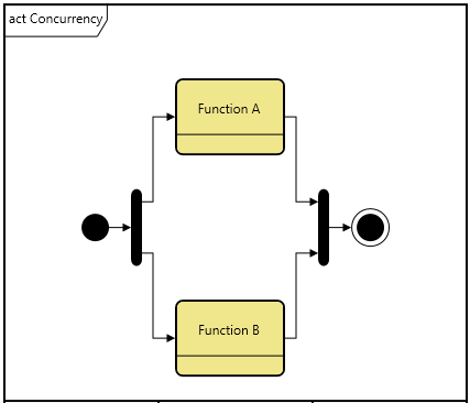
A parallel construct consists of an AND node, followed by separate branches that rejoin and terminate at another matching AND node. Each branch can contain any number of functions and control constructs. In contrast to sequences of functions and control constructs where the next entity cannot be executed until the previous one completes, the parallel construct designates that the parallel branches can be executed concurrently (even though they may interact through triggers).
When executed by the simulator, the first entity on each branch will be enabled at the same simulation clock time. The construct cannot be exited (from the second AND node) until all branches have completed their processing. Control is then passed to the next function or construct after the parallel construct.
Select 

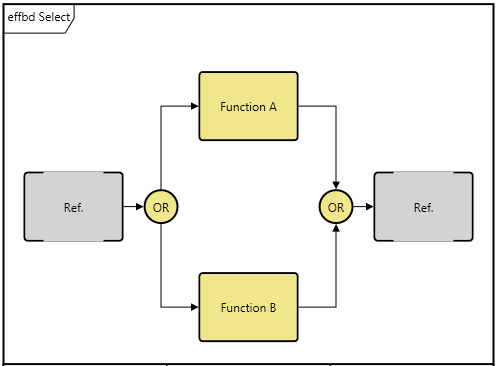

A select construct consists of an OR node followed by multiple branches that rejoin at a matching OR node. Each branch can contain any number of functions and control constructs. In contrast to a parallel construct in which all branches are executed, with a select construct only one branch is executed. Thus, the select construct is an exclusive OR.
Each branch may be assigned a selection probability to determine the likelihood of execution during the simulation. If there are no branch selection probabilities, each branch will have equal likelihood of being selected for execution.
Loop 

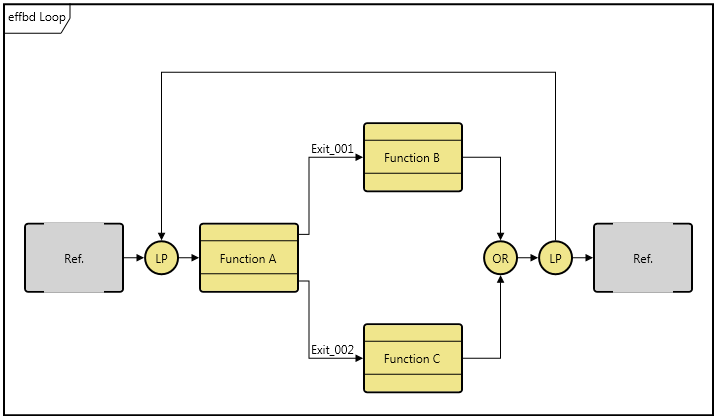
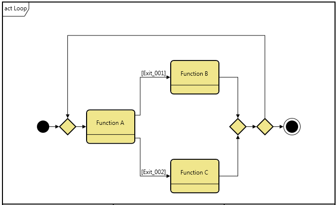
A loop construct consists of a pair of LP nodes that enclose a branch and are connected with a loop back line. The branch can contain any number of functions and control constructs. These will be repeatedly executed in sequence. The branch will typically contain a loop exit construct to conditionally exit the loop construct. Without a loop exit, the loop construct becomes an endless loop.
A descriptive annotation should be specified for each loop construct. The annotation is displayed above the loop back line. This annotation is only descriptive and does not impact execution.
Loop Exit 
The loop exit construct provides the mechanism for exiting a loop. When the loop exit construct is encountered, the innermost loop is immediately terminated, enabling the construct or function following the loop.
Iterate 
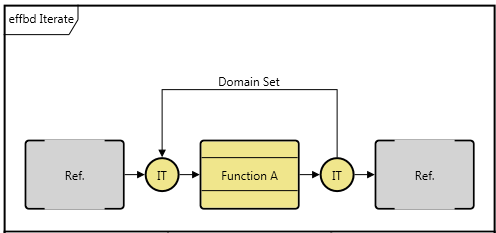
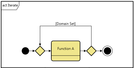
An iterate construct consists of a pair of IT nodes that enclose a branch and are connected with a loop-back line. This line is automatically labeled with the name of the associated DomainSet entity.
The branch can contain any number of functions and control constructs. These will be repeatedly executed (in sequence) the number of times predefined by the domain set count attribute.
If the count attribute of the domain set is not set, the number of iterations will revert to the system default as specified in the simulator preferences.
Replicate 

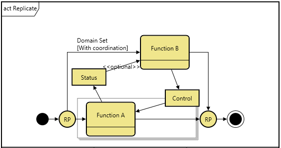
A replicate construct consists of a pair of RP nodes that enclose a main branch and are connected with a coordination branch. This coordination branch is automatically labeled with the name of the associated DomainSet entity.
The replicate construct is a shorthand notation for identical processes that operate in parallel. The main process logic is shown on the main branch. The coordination between these processes is handled via the coordination branch. An example of a situation handled by the replicate would be a supermarket in which multiple checkout lanes support shoppers (represented by the functions on the main branch) and a manager supports the various checkout lanes as required (represented by the functions on the coordination branch).
Exit Node 


In the case of a multi-exit function, exit nodes establish the mapping between the completion of the decomposition behavior and the exit branches of the parent function. There should be at least one exit node in the function decomposition for each exit branch for the function. The name for the corresponding exit branch is shown below each exit node icon.
When an exit node is encountered during simulation, the decomposition level is exited and the corresponding branch of the multi-exit function is followed.
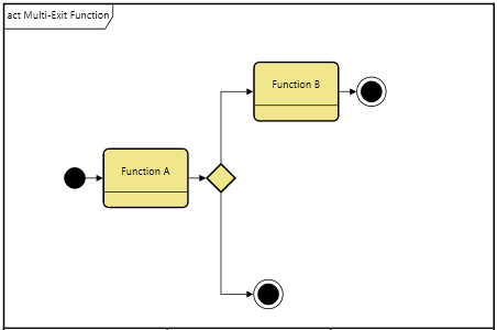
Multi-Exit Function 
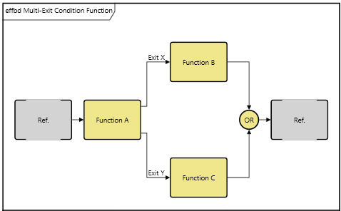

A multi-exit function is a control construct where multiple branches exit from a function and rejoin at an OR node. Each branch is labeled with the name of its associated exits and can contain any number of functions and control constructs. The criterion for selecting which exit branch to follow is specified by the function, either using a selection probability attribute associated with the exits by relationship or by scripting logic embedded within the exit logic attribute of the function. If there are no exit probabilities and the exit logic attribute is empty, each branch will have equal likelihood of being selected.
One would normally use a multi-exit function construct in lieu of a select construct when the selection criterion can be specified by scripting logic in the exit logic attribute or via a corresponding exit node within the functions decomposition.