Node Templates 
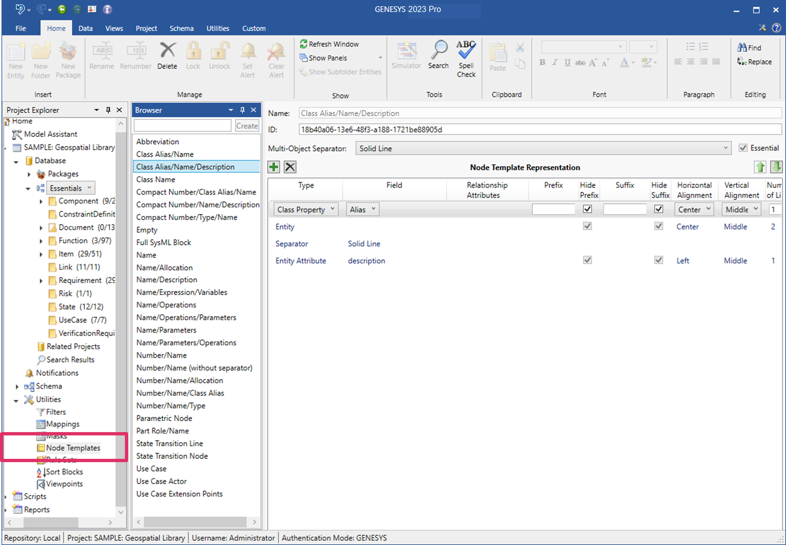
The Node Templates item in the Utilities section of Project Explorer enables you to define how entities are displayed on diagrams. Node templates are designated in Project Preferences but can be assigned at the diagram level to customize a given view. This provides project teams tremendous richness in representing and communicating the system model.

Node Templates
The Browser pane lists all defined templates in alphabetical order. Node templates are defined on a per-project basis, enabling each project to maintain the collection of templates that best meet their needs. When you select a template, the settings for the selected template are shown in the property sheet.
|
NOTE: |
GENESYS uses the same template for either single-object nodes or for multi-object nodes. Most diagram nodes represent a single object. However, select diagram nodes (most notably the connecting nodes on an N2 diagram) can represent multiple entities. When used on a multi-object list, the template is displayed on a single line with the designated separator used to separate each entity displayed. |
Property Sheet
For each node template, the properties include:
- Name - the unique identifier of the selected node template. There are no formal restrictions on the name.
- Multi-object separator - the line separator between multiple entities.
- Essential - a flag indicating whether or not this node template is required by GENESYS. Essential templates cannot be renamed or deleted.
- Representation - the ordered collection of fields to include on the node. Field types include:
- Class Property - a property on the class of the entity
- Composite - This type allows for multiple values to be displayed on the same line in the node. Entries included in this grouping will be shown with an arrow at the beginning of the line.
- Entity - the name of the entity
- Entity Attribute - an attribute value for the entity
- Entity Parameter - a parameter value for the entity
- Entity Property - a property for the entity
- Relationship - the targets of the relationship for the entity
- Relationship Attributes - the value of the relationship attribute
- Separator - the type of line to separate the other entries. Note that if this is included in the Composite grouping all selections will appear as a solid line.
- Text - literal text
Columns are available with each representation entry:
- Field Type - selected from the list of representations above.
- Specification - selected from the project schema based on the field type.
- Relationship Attribute - if the field type is relationship, this column contains the desired relationship attribute for the specified relation (can be left blank).
- Prefix - text output before the data is output.
- Hide Prefix - checked means to hide the prefix if there is no data for this line, unchecked means to show this text regardless.
- Suffix - text output after the data is output.
- Hide Suffix - checked means to hide the suffix if there is no data for this line, unchecked means to show this text regardless.
- Horizontal Alignment - where this output appears horizontally on the node.
- Vertical Alignment - where this output appears vertically in the space allocated for this line.
- Number of lines - how many lines of the node are allocated to this output.
- Width - how many pixels are allocated to this output. Note that this is used only for entries included in a Composite grouping.
- Fill Space - nodes usually have more space than number of lines or the width specified in the node template. When this is checked, this is where the excess lines or width should be used.
To add a new field to the node template, use the Insert button to add a field below the selected field. To remove a field, select and select the Remove button. To move a field, either use the arrow keys to move the selected field up and down one position at a time (moving into and out of a ccomposite group if encountered) or drag and drop the field.
|
NOTE: |
If more than one entry has a fill space either for the node or for the composite group, the extra space is divided proportionally among them. |
Node Template Commands