General Diagram Project Preferences
Certain settings and behaviors are common across the various classes of diagrams. The general diagram preferences allow you to control these settings.
 |
Unlike the options for a specific class of diagram, these options cannot be adjusted for an individual diagram. In other words, though you can choose whether or not to display a frame on a specific diagram, you cannot customize the frame block contents to differ from what is specified in your user preferences. This helps ensure consistency (and avoid unnecessary complexity) across your diagrams.
|

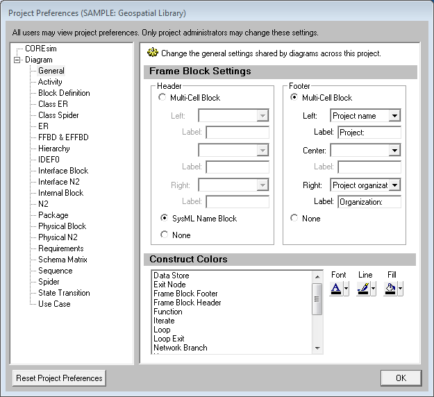
Frame Block Settings
To properly label your diagram and provide critical context information - for the specific object or the project - this setting allows you to define the style and content you wish to display on your frame blocks. For example, you could display the performing component in the frame of an activity diagram or the security classification level in secure environments.
-
SysML headers display the diagram type and the name of the object
-
Mutli-cell blocks support up to three cells (left, center, and right), each with a corresponding user-defined label. Possible cell contents include:
-
-
the object name
-
object attributes
-
object relationship targets
-
object folder
-
select project properties (the project name, the organization, or the customer)
-
current date
Header - specify the header to display at the top of the diagram frame. You can choose between a classic engineering-style header with one, two, or three different cells; a SysML header; or no header whatsoever.
Footer - specify the footer to display at the bottom of the diagram frame. You can choose a classic engineering-style footer with one, two, or three different cells or no footer whatsoever (if you prefer a classic SysML frame, for example).
Construct Colors
The construct settings allow you to set default font, line, and fill color for icons displayed on diagrams based upon the construct. This is particularly useful on activity diagrams and EFFBDs.
The order of precedence CORE uses when drawing a specific node on a diagram is as follows. If a color setting is nil/automatic, CORE will continue to move down the list until it identifies the color to be used:
-
Colors applied directly to the specific node on the specific diagram (set using the toolbar buttons on the diagram)
-
Colors specified for the element font, line, and fill attribute fields (set on the secondary tab of the element property sheet)
-
Colors specified for the element class font, line, and fill properties (set on the class property sheet)
-
Colors specified for the node construct type (set in the General Diagram category of the user preferences)
-
Node colors specified for the diagram type (set in the Diagram Options)
